Install CATIA V5R21 on your system and then start it by
double-clicking on its shortcut icon on the desktop of your computer. You
can also choose Start > All Programs > CATIA > CATIA V5R21 from the
taskbar to start the program.
After the
system has loaded all required files to start CATIA V5R21, a new product file,
with the default name Product 1 will start automatically, as shown in Figure 1
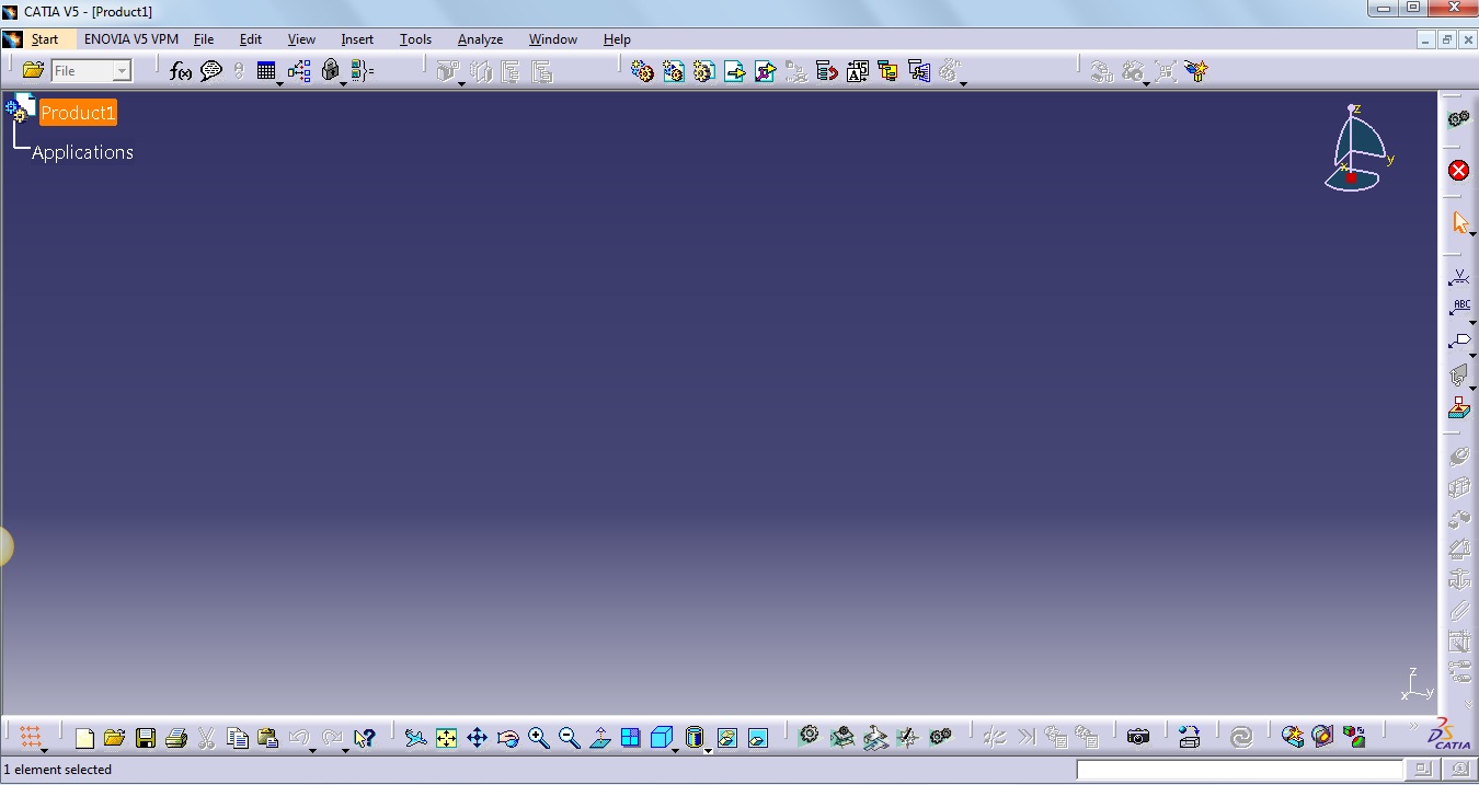
Close this file by choosing File > close from the menu bar.
Figure 1.1 shows the screen that appears after closing the initial product file.

Figure 1.1 The screen that appears after closing the initial Product file.
Goto Start > Mechanical Design > Part Design
The
main window of CATIA V5 is similar to a normal Windows program, with its File-Edit-View
menus. At the right of the main window are located the icon commands
that are specific to each CATIA workbench. At the bottom of the main window are
located the general icon commands used in nearly all workbenches. Icon commands
are usually located at the bottom and right of the screen but they can also be
added to the left and at the top (below the main commands) as you see fit.
CATIA’s
design area can be divided into two main sections:
Specification
Tree : The structured information describing the design
process.
This is a very important tool to understand the product structure
(It
is the core feature of designing with CATIA V5).
Geometric
Area : This is where geometrical elements actually takes
place.
It
is always located behind the specification tree and can occupy all the screen.
No comments:
Post a Comment